Thursday, September 16, 2010

WIRING

In choosing a control system for my Michigan South Central layout, I wanted a system that would be both simple to install and simple to operate. I decided to stay with the tried and true cab control using common-rail wiring. It works perfectly for me, and the thought of adding decoders to the eight engines isn't in the budget.

The Control Master 20 by MRC was my power pack of choice. The CM-20 comes with a handheld throttle with memory that plug into standard telephone jacks. These allows me to run a train, unplug the throttle from the jack, and move to another jack while the train keeps moving at the same speed and direction. I needed two CM-20s, but at $200.00 bucks apiece I knew for a fact I didn't want to spent that kind money. Ebay was the answer for this problem. I won one for $95.00 dollars including S&H in April 2009, and the other for like $100.00 dollars including S&H in July 2009. Combine I didn't spend the money for the price of one. Good Deal!


After getting the second CM-20, I noticed that they were different. The 2nd CM-20 didn't have a cooling fan and I thought I've been had. It turned out that there are two different versions of the CM-20. Version 1 has a 80VA output with a cooling fan and Version 2 has a 100VA output that doesn't. Glad I found that out before giving the seller on Ebay a piece of my mind.

I spent the following months gathering all the other materials needed to wire up the layout. My intension was to wire the layout over my 4 day Christmas weekend and my 4 day New Years weekend. I got started on wiring the layout on December 27, 2009, using a color code system to keep the wires organized and to cut down on mistakes, which do happen. Kato Unitrack uses blue and white wire in its terminal track, so I choose blue for the blocks and white for the common rail. For the two throttles I used red wire for one and black for the other. I drilled holes thru the foam and plywood where the feeder wires will go. Next I put in two terminal strips at each end of the layout and ran the common rail bus wire for the lower level part of the layout between them and called it a day. I used white 12-gauge stranded wire for this.

Wiring was in full swing the following weekend. I installed the common rail wire for the upper level, this time using 14-gauge stranded wire. Why 14-gauge you ask? The 50 feet of 12-gauge I had purchased from Lowes wasn't enough so I had some white 14-gauge wire left over from earlier layouts and used that. I connected all the white feeder wires from the track to the common rail bus and that portion of wiring was done.

The power pack wires was the next thing on the list to do. I used a spool of red and a spool of black 20-gauge wire from Atlas for this. I ran the red for cab 1 and black for cab 2 around the front of the layout to the terminal strips at each end.


Constructing the six control panels need to operate the layout came next. The control panels consist of a Plexiglas front, paper with a color schematic drawing in the middle, and the base, which is the fascia of the layout. The panels also have SPDT center off toggle switches showing the blocks condition: Left = Cab 1, Center = Off, Right = Cab 2.


I didn't want the panels to take up a lot of space on the fascia so I decided to make them 4.25" high by 14" long. This size allowed me to print out two decent size schematics on one sheet of legal size paper. I drew the schematics on my computer using the XtrkCad program and printed them using a color printer.

The only difficult part of building the panels was the cutting of the Plexiglas. I used the score and snap technique to get the size panels I needed using a Plaskolite Optix knife. Once this was done, I drilled four small holes in each corner of the Plexiglas for the mounting screws. I took my time doing this because I didn't want to crack the Plexiglas.

Now I mounted the paper schematic and Plexiglas on the fascia and drilled small pilot holes for the toggle switches. I had to be careful not to drill holes near a girder in the benchwork because it would interfere with the installation and wiring of the toggle switches. I used a bigger bit to drill the final holes for the toggle switches and then installed them from the back of the fascia through the holes on the control panels and screwed on the toggle switch nuts. I wired the toggle switches using the daisy chained method instead of individually, which uses less wire and makes the panels look neater. The switches I got had screws in them to make wiring them easy. NO SOLDERING!


I built a small shelf under the staging area of the layout for the base units for the two MRC Control Master 20 power packs to rest on and then wired them up.


The handheld throttle on the CM-20 use a standard four wire telephone cable and connectors. I put in six one-jack phone plates in three handy locations around the fascia. Three for cab 1 and three for cab 2.


I wired them up using standard telephone cable from cab 1 to jack of the first plate. I ran another set of wires from this to the jack of the second plate, then another set wires to the third. I repeated the process for cab 2. Now that I had the layout wired, I checked it out!  I placed an engine on the track, turn on the power, and ran it on every single inch of track. Just my luck, I had a couple of blocks wired to the wrong toggle switches on one of the control panels. Never fails when its come to wiring. I really enjoyed making my control panels. They are simple and easy to understand, even a caveman can read them.


Wednesday, September 15, 2010

FASCIA

After months of doing nothing to the layout, I finally got started on the Fascia on 6-28-09. I went with a 4x8 sheet of 3/16 Masonite hardboard which I got back on 4-11-09 from Lowe's for $12 bucks. I had them to cut the sheet into four 1x8 sheets. All I had to do was make the final cuts to the right length to match the benchwork. Shoulda had Lowe's to do that too!

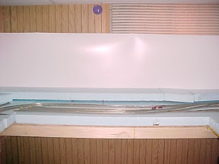
I align the top of the Fascia with the top of the plywood and not the foam. I will bevel the foam down to the Fascia to make a soft edge which will get rid of the table-top look.


I couldn't make up my mind on what color to paint the Fascia, black or green. The green would blend with the scenery around the edges and the black would make the eye focus more on the top of layout. I went with a semi gloss black. I went to Lowe's the following morning, pickup a small can of paint, and had the Fascia painted by mid afternoon.


Once the paint dried, I beveled the foam down to the Fascia. It got rid of the flat look from the edges of the layout. Messy work! Blue particles all over the place again!


FOAMBASE

I got started on the foam base of the layout on 02/21/09. I when to Lowe's and purchased three blue 4x8 2" thick foam boards along with some Olympic Arabian Sands paint, painting utensils, wood glue and lights for the room. I don't know about Home Depot's 2 thick boards but Lowe's has score lines already in the boards. It was easy handling the boards by snapping them into 2x8s. I used a serrated steak knife to cut the boards to the shape and sizes I needed. For final contouring I used a Surform tool, a very messy way by doing it like this. There was small blue particles stuck to everything after I was done!

I used wood glue to secure the lower level foam boards to the OSB. I didn't secure the foam for the upper level because I still needed to shape the foam so that it won't interfere with the lower level track.


LANDFORM

After carving and shaping the foam on the lower level and getting those blue particles everywhere, I decided to go with a less-messy way of carving the foam for the upper level. So I went to the Hobby Shop and purchased the hot wire tool from Woodland Scenics. This was a complete waste of $40.00. I had a very hard time cutting and shaping the 2" foam with this thing. It was slow and the wire kept breaking. I went back to the messy way of cutting and shaping the foam. After gluing the upper level down I used plaster cloth to cover the gaps between the foam boards.


After the plaster cloth had dried, I painted the layout with the Olympic  Arabian Sands with a roller. Where the foam meets the backdrop, I used a Shur-Line Paint Edger to keep from getting the tan paint on the backdrop.


 I put the track back together so I could know where to place the Woodland Scenics 2% Incline Sets to get the track between the two levels. I used wood glue and foam nails to properly place the inclines.


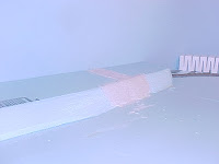
The only thing I don't like about the Incline Sets is that they have an unnatural square like look. I fixed this problem by gluing scrap foam in the front and in the back of them.


After the glue had set, I covered the Incline Sets and scrap foam with plaster cloth and gave it a coat of paint. Now it has a more natural look.


LIGHTING

I decided to install the lights for the layout on 02/28/09. I wanted something inexpensive, simple and easy to install into my drop ceiling. I purchased Utilitech 5-Lamp String Light for $60.00. The lights are spaced 10 feet apart and just can be plugged into any outlet.


I simply cut holes into the ceiling tiles where I wanted the lights to be and ran it over the top of the drop ceiling and back out into an outlet. I didn't used the yellow cages that came with it, I just installed five of those energy saving 20w CFL Bulbs.


Tuesday, September 14, 2010

BACKDROP

My two previous layouts didn't have a backdrop so I decided that this one will. I want to take pictures of this layout and I didn't want paneling as my backdrop. I was going to go with Masonite for my backdrop until I posted a question on the Atlas N-Scale Forum and was told about Vinyl Flashing. Its comes in a large roll and easy to use. When I was at Home Depot getting my OSB, I went to check out this stuff. To my surprise they didn't carry it, website order only. Off to Lowe's with OSB tied to the roof of my car. Lowe's did carry it and for a 50' roll 20" wide it was $48.00. Ouch! I priced 3 sheets of Masonite and it came to about $38.00. I went with the Vinyl Flashing due to the fact that I won't have seams to fill and its looks much easier to handle than the Masonite.


Got started on the backdrop on 01/31/09. I secured a few feet of the Vinyl Flashing with a couple of C-clamps just to see how it would look. This stuff is so thin! What to secure it with, screws, nails, or adhesive of some sort. Then I remembered seeing some Velcro strips at the $1 store. So off I went. 1 pack comes with 12 sets of very strong adhesive tabs so I got 10 packs. Just might work!


I put the tabs together exposing the adhesive and placed 3 of them on the first 1 x 2. The adhesive on the tabs stuck well to the 1 x 2. With the glossy side towards the studs I unrolled about five feet of the Vinyl Flashing and secured about three feet of it with my C-clamps. Working from top to bottom of the stud I pressed it onto the tabs. Instant securement! It took me a couple of hours to do the whole room. I got curved corners and no seams.


I don't know if securing the Vinyl Flashing like this is going be the long term answer but it was so easy doing it like this. No screws or nails to cover up! A least for now! All I got to do now is paint it. Hopefully the Olympic Flemish Blue I got is the answer to a good looking sky.


I painted the backdrop with the Olympic Flemish Blue on the morning of 02/28/09.


BENCHWORK

The L-Girder benchwork got started on the morning of December 26, 2008. Most of it was completed that day. The L-Girders and backdrop supports are made from 1 x 2s and the joists are 1 x 3s. I wanted to be able to store items underneath the layout when completed so I made the legs from 2 x 2s cut 48 long. Being this high off the ground will make it easier to work on the layout sitting on a small stool or a milk crate.


On January 2, 2009 I went to Home Depot and purchased 3 sheets of 1/2 OSB and had the store cut it to the sizes I needed. I chose OSB over plywood because of the price, its much cheaper! I install the OSB along with the rest of the backdrop supports that day. Once I did that I went on ahead and laid out the preliminary track plan just to see what will fit.


I won't lay down the foam base until I put in the backdrop. For now I will just tinker with the track plan. Need to purchase more track!